NEWS
Power SCADA System
Is it promising to apply a Power SCADA system in the power industry?
The advantages of applying a Power SCADA system to energy management, specifically electrical power management, are very promising.
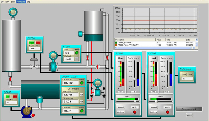
Remote control of devices and monitoring the operating status of each area at a 1:1 scale through SCADA software. The collected data is stored and can be easily accessed, with detailed data reporting charts and graphs.
With the mission of delivering breakthrough solutions, ATSCADA LAB has researched and developed SCADA, upgrading it to ATSCADA. It provides a comprehensive solution for remote monitoring, control, and data acquisition applications.
The advantage of ATSCADA lies in its distributed system functionality.
The power industry is a rapidly developing sector and is one of the most thoroughly invested industries in every country. To develop in line with the Industry 4.0 trend, a Power SCADA system is an essential factor to keep up with today’s Industry 4.0 technology.
What are the advantages and disadvantages of applying a Power SCADA system in the power industry?
Advantages:
- Ensures high capability for remote operation and monitoring of high-voltage and medium-voltage power grids.
- Improves operational management efficiency.
- Enhances the reliability of power supply.
- Improves the skill level of operation, repair, and maintenance personnel.
- Collects, processes, and stores system data.
- Enables remote control of switching operations: circuit breakers, disconnect switches, and grounding switches.
- Allows remote adjustment to increase/decrease transformer voltage.
- Enables remote control of transformer cooling fan systems, etc.
Disadvantages:
- To ensure stable operation of the power grid, the Power SCADA system has no disadvantages.
ATSCADA LAB provides consultation and support for installing SCADA systems in the power industry, steel plants, water plants, thermal power plants, substations, wastewater treatment systems, etc.
General introduction to the Power SCADA system.
The communication port of an RTU typically uses serial communication methods through RS232, RS485, or RS422 interfaces.
For the Power SCADA system of the National Load Dispatch Center, there are four basic types of data:
Analog Input Data (Analog Input – AI).
The system encodes each AI channel using 16 bits to measure physical quantities such as power, current, voltage, and transformer tap position.
The system converts these quantities into intermediate electrical values such as voltage (U) or current (I), then sends them to the RTU through an analog card.
In the Power SCADA system currently used at the National Load Dispatch Center, engineers use current as the intermediate value because it provides a major advantage: it does not suffer signal loss in the measuring circuit when the transducer is installed far from the RTU. Therefore, the RTU measurement results accurately reflect the actual values.
Digital Input Data (Digital Input – DI).
The system encodes DI data using 1 or 2 bits to display alarms and device statuses, such as protection alarm signals (differential protection, distance protection, overcurrent protection, etc.) and the status of circuit breakers, disconnect switches, and grounding switches.
Engineers use intermediate relays with suitable voltage ratings to connect and electrically isolate the RTU from the substation or power plant control system.
Analog Output Data (Analog Output – AOT).
The system encodes AOT data using 16 bits to adjust continuously variable quantities. Dispatching centers send adjustment commands to the RTU, and the RTU converts these commands via D/A into a current signal (mA) to drive the actuator mechanism.
In the Power SCADA system currently used at the National Load Dispatch Center, operators use AOT data to adjust the active power (P) and reactive power (Q) of generating units.
Digital Output Data (Digital Output – DOT).
The system uses 1 or 2 bits to control the positions of devices in the power system, such as circuit breakers, disconnect switches, and grounding switches.
Engineers use intermediate relays with voltage ratings compatible with the DOT card output voltage to connect and isolate the RTU from the substation control system. The relay auxiliary contact current must be high enough to meet the actuator mechanism requirements.
Connecting the RTU to the Power System (PS).
Analog signal interfacing:
For signals such as P, Q, U, and I, engineers use transducers to convert current, voltage, and Cos(φ) signals into proportional current signals.
As for frequency signals, engineers use transducers to convert f (Hz) into proportional current signals.
Regarding transformer tap position indication signals, engineers use transducers to convert R (Ω) into proportional current signals.
Digital signal interfacing:
For digital signals, intermediate relays are used to interface the power system with the RTU.
Analog output signal interfacing:
For analog output signals, the output signal is directly connected to the actuator mechanism of the control system.
Digital output signal interfacing (DOT):
For digital output signals, intermediate relays are used to interface the power system with the RTU.
Database in the Power SCADA System
Tasks:
- Describe the hardware configuration and existing RTU I/O boards.
- Initialize parameters for the communication port between the RTU and the control center.
- Configure RTU I/O channels corresponding to the signals collected at the substation.
- Map I/O channels to the corresponding IOA addresses at the control center.
Structure:
To perform the above tasks, the database structure differs depending on RTU types from different manufacturers. However, basically, the RTU database is composed of modules as shown in the diagram…
The RTU includes 3 PAI, including:
PAI 1: Manages the Analog Input and Analog Output boards. In addition, BAY 1 is responsible for acting as the communication gateway, managing communication port configuration parameters (IEC GEN), and managing IOA addresses transmitted to the control center (IEC MAP). The IECGEN and IECMAP modules always go together in the same BAY. Each RTU may have one or multiple communication ports depending on the hardware configuration.
PAI 2, 3: Manage the I/O boards: Analog Input, Digital Output, and Digital Input (DI). DI boards can be used in Single DI (SDI) or Double DI (DDI) form.
Auxiliary Equipment for the Power SCADA System
UPS Power Supply
The UPS system ensures continuous power supply for the Power SCADA system at the Control Center.
The system includes two UPS 911 units connected in parallel. Each UPS unit is connected to two 220VDC battery banks.
When the grid power fails, the battery banks supply power through an inverter, converting DC voltage into 220VAC.
Operation in normal mode:.
In normal operation mode, the UPS system continuously provides stable and uninterrupted power for the host computer system at the National Power System Dispatch Center.
Operation in battery mode occurs in one of the following cases:
- Grid power outage.
- Grid power is available but technical parameters (voltage, frequency) exceed allowable limits.
Supplying load power from the grid occurs in one of the following cases:
- Battery voltage is low.
- Switching to maintenance mode.
- Rectifier failure; inverter failure.
- UPS system overload.
Basic technical specifications
- Number of UPS units: 02.
- Capacity of 1 UPS: 15KVA.
- Number of battery banks: 04.
- Battery capacity: 45KVA.
- The system includes two UPS 911 units connected in parallel. Each UPS unit is connected to two 220VDC battery banks.
Diesel Generator System
Overview
- Diesel engine capacity: 30 KVA.
- Includes a generator and batteries for diesel startup.
- When grid power is lost, the diesel system automatically starts to supply power to the load.
Communication System
The communication system at the control center includes devices and transmission channels that ensure voice communication between power system dispatch engineers and on-duty personnel at substations and power plants for power system operation management.
Hotline channels
A hotline (emergency) connection is a direct voice connection between two stations. The caller only needs to lift the telephone handset, and the system automatically connects the call to the remote end (the remote address is predefined).
Currently, there are more than 50 hotline channels connecting A0 with substations, power plants, dispatch centers, and transmission centers.
Dial-up channels
Dial-up channels connect subscribers to the switchboard (electricity sector or telecom). Operators communicate with another subscriber by dialing the required phone number. Currently, the dispatch switchboard also connects to some dial-up subscribers in both the electricity sector and the telecom sector.
Radio channels
In addition to dial-up phone and hotline communication as mentioned above, communication via radio transceivers is also used (currently used at the Southern Power System Dispatch Center). Characteristics of this communication method include:
- Wireless communication, limited by distance and terrain.
- Half-duplex communication (at a given time, only speaking or listening is possible).
- Only applied in certain special situations.
Dispatch Switchboard (Lineseizer – LSZ)
Overview
Instead of placing many telephones on the desk, the LSZ device allows all communication channels (excluding radio channels) to be consolidated and operated through 03 telephone control consoles, with 03 digital telephones and 03 keyboards.
Main features of LSZ:
- Ensures hotline connection to multiple locations.
- Easily identifies incoming calls accurately (especially during incidents when there are many incoming calls).
- Easy operation when making outgoing calls to specific addresses.
- Currently, the switchboard can connect up to 64 channels (hotline and dial-up).
- The switchboard can be expanded when required.
Voice Recording Equipment
Overview
Records conversations between dispatch engineers and on-duty personnel at power plants and substations to support analysis of incident situations in power system operation.
Currently, the control center has 2 recording devices:
- Marathon industrial voice recording system (main device).
- Backup recording system using channel interface cards and a PC, operated when the main device has issues.
Industrial Voice Recording Equipment
General introduction
ASC Telecom manufactures the MARATHON PRO digital voice recording device, a modern recording system with 128 input channels that can connect to telephone lines, telefax machines, or wireless communication devices. Operators control the device using a keyboard and a built-in mouse locator ball on the front panel.The LCD screen on the front displays all necessary information for monitoring and operating the device.
Technical features
- Continuous operation 24/7.
- Capable of recording and monitoring 128 calls simultaneously.
- Expandable connectivity (by adding channel interface cards).
- Large storage capacity (100,000 hours).
- Stores data both on hard drives and tape.
- Allows monitoring of channel status through a channel monitoring screen.
- Supports searching recorded calls based on different criteria (call time, channel number, etc.).
- Can store important calls separately for easier retrieval.
Backup Voice Recording System (PC + Recording Card + Recording Software)
General introduction
The backup recording system uses channel interface cards installed on a PC. Data is recorded directly to the PC hard drive. The system can be directly connected to transmission channels or to audio frequency signal sources. It provides a user-friendly interface and supports multiple recording start methods, along with many utilities for storing and searching calls.
Technical features
Currently uses 01 card interfacing with 08 analog channels.
Expandable connectivity.
Can simultaneously record up to 32 calls on the channels.
Can monitor ongoing recorded calls.
Stores data on the computer hard drive.
Ensures safe and reliable access management through usernames and passwords.
Frequency Measurement and Synchronism Monitoring System (DHZ)
The Frequency Measurement and Synchronism Monitoring System (DHZ) monitors power system frequency and synchronism by collecting measurement data from major power plants and key substations, then transmitting the data to dispatch centers such as A0, A1, A2, and A3 through 4W channels and modems. Operators display frequency values on computer screens and large analog meters in control rooms to support real-time monitoring and system stability. The DHZ system measures frequency by calculating the signal period using a crystal oscillator pulse, providing high accuracy of ±0.01Hz within the range of 45.00Hz to 55.00Hz, with a data update cycle of 1 second (adjustable).
The frequency measurement system includes measurement devices installed at important power plants in the power system and at the A0, A1, A2, and A3 control rooms.
Frequency measurement points include major facilities such as the Hoa Binh, Tri An, Yaly, Phu My, Pha Lai, and Thac Ba power plants, as well as the 500 kV Phu Lam substation. In addition, the system also installs synchronism monitoring devices at the 500kV substations in Ha Tinh, Da Nang, and Pleiku to monitor the 500kV transmission line.
The system transmits frequency and synchronism data to A0 through 4W channels and modems.
Operators display frequency values on computer screens. They also display the frequencies at both ends of the 500kV line (T500 Hoa Binh and T500 Phu Lam) on two large analog meters in the control room.
The system also transmits frequency values to the control rooms of regional dispatch centers (A1, A2, A3).
The principle of frequency measurement is based on measuring the signal period length using a crystal oscillator pulse, then calculating the frequency.
Frequency measurement accuracy is ±0.01Hz across the measurement range of 45.00 to 55.00Hz.
The measurement and data transmission cycle is 1 second (adjustable).
Frequency measurement via Power SCADA system
Disadvantages of using the Power SCADA system to measure power system frequency at RTU locations:
- Frequency transducers in RTUs are analog, so even after digitization, accuracy cannot exceed the transducer’s accuracy.
- Frequency transducer accuracy does not meet the required 0.01Hz across the full range.
- The host computer scan cycle is several seconds, which is too slow compared to the requirement.
- Dispatch centers A0, A1, A2, and A3 currently do not monitor power system frequency through the Power SCADA system.
Operation and management
The Technology Department of the National Power System Dispatch Center designed and manufactured the frequency measurement system, so they fully control inspection and repair internally.
- Monitoring system operation status through the dedicated frequency program interface.
- Monitoring the remote-end connection status via modem indicator lights.
Telecommunication Channels for SCADA Connectivity
The SCADA server connects to terminal devices (RTUs) through 4W channels and audio-frequency modems.
Channel characteristics:
- 4W audio-frequency (analog) channel.
- Line impedance: 600Ω.
- Bandwidth: 300Hz to 3400Hz.
- Complies with recommendation G.712.
ICCP connection channel
ICCP (Inter Control Center Protocol) data is sent from Power
SCADA systems at A1, A2, and A3 to A0.
The ICCP transmission channel is an E1 stream connecting A0 – A2 – A3 and a backup channel provided by EVNTel.
>> Click to see how to work with ATSCADA
ATSCADA - Providing ATSCADA software - The monitoring and data acquisition control system is the appropriate choice for integrated system projects, IoT, smart city projects, agriculture 4.0... Is trusted by many customers.
Related posts
ATSCADA – The Best SCADA Software Download for Industrial Automation
If you are searching for a reliable SCADA software download, ATSCADA is a powerful solution [...]
Apr
ALL ABOUT SCADA SYSTEM
The SCADA system is the combination of hardware devices and software that allows monitoring and [...]
Oct
HOW TO USE SYMBOL FACTORY IN SCADA SOFTWARE
Using Symbol Factory in SCADA software is an outstanding solution for designing HMI or SCADA professionally. Let’s find [...]
Oct
SCADA – IoT: Công Nghệ Bổ Sung Cho Công Nghiệp 4.0 Hiện Đại
Công nghiệp 4.0 đang tạo ra sự thay đổi lớn trong cách các doanh nghiệp [...]
Sep
Hệ Thống Giám Sát Nhiệt Độ Kho Lạnh Vaccine: Giải Pháp An Toàn & Hiệu Quả
Bảo quản vaccine ở nhiệt độ lý tưởng là công việc vô cùng quan trọng [...]
Jul
Giải pháp kiểm tra tiếp điểm rơ le
Giải pháp kiểm tra tiếp điểm rơ le là một thành phần không thể thiếu [...]
Jan