Technical Guides
UART Communication Explained: Working Principle and Applications
Electronic applications widely use UART communication to transfer data between devices such as computers, microcontrollers, sensors, and more.. It utilizes two independent signals, TX (Transmitter) and RX (Receiver), to send and receive data in the form of data frames.
So, what is UART communication? In this article, atscada.com will provide a complete overview of UART, helping you understand how it works and where it is applied. Stay tuned!
What is UART communication?
UART stands for Universal Asynchronous Receiver-Transmitter, which refers to an asynchronous data transmission method. It is a serial communication protocol that allows data to be transmitted and received through two separate lines (excluding the ground line).
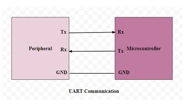
UART is a simple and widely used protocol that consists of two independent data lines: TX (Transmit) and RX (Receive). Data is sent and received through these lines in the form of structured data frames, including one start bit, several data bits, an optional parity bit, and one or more stop bits.
UART communication transmits serial data in one of the following three modes:
- Simplex: one-way communication
- Half-duplex: data flows in only one direction at a time
- Full-duplex: simultaneous bidirectional communication between master and slave
The TX (Transmit) pin of one device directly connects to the RX (Receive) pin of another device, and vice versa. Systems typically operate UART communication at voltage levels of 3.3V or 5V. In most cases, UART communication occurs between one master and one slave, with each device configured to communicate with only one counterpart.
The controlling device handles data in parallel before sending it through UART. When transmitting via the TX pin, UART converts the parallel data into a serial format and sends it to the receiving device. The RX pin of the receiving UART then converts the serial data back into parallel form for communication with the control system.
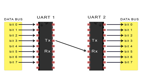
Data transmitted via UART is packaged into frames. Each data frame includes one start bit, 5 to 9 data bits (depending on the UART configuration), an optional parity bit, and one or two stop bits.
The UART transmission process occurs in the form of these data frames, beginning with a start bit where the signal transitions from high to low. Following the start bit are 5 to 9 data bits transmitted within the frame, then an optional parity bit. Finally, one or more stop bits are sent at a high signal level, marking the end of the data frame transmission.
Key applications of UART communication
UART protocol is widely used in various fields, such as:
Communication between microprocessors and peripheral devices
UART enables communication between microprocessors and peripheral devices such as LCD displays, sensors, printers, barcode scanners, and more. It allows the microprocessor to easily access and control the functions of these peripherals.
Connecting computers with peripheral devices
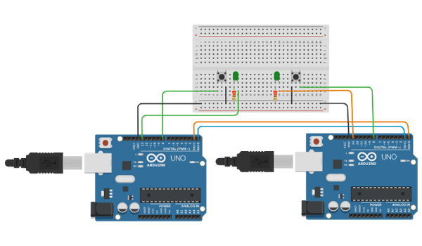
In some cases, UART connects computers with peripheral devices through serial ports or USB-to-UART converters. This enables computers to communicate with devices such as Arduino boards, development boards, Raspberry Pi, and more.
Wireless data transmission
Nowadays, Bluetooth and Wi-Fi modules use UART to enable wireless data transmission between devices. In this setup, UART communicates with wireless control circuits, allowing mobile devices, computers, embedded systems, and wireless modules to exchange data efficiently.
Measurement systems
UART connects measurement devices with other systems to transmit data, allowing the receiving device to display or further process the information.
Although many modern communication technologies have emerged, UART still remains a preferred choice for many electronic applications thanks to its simplicity, flexibility, and efficiency.. We hope the information provided by atscada.com in this article has given you a comprehensive understanding of UART communication.
If you have any questions or need further assistance, please contact our sales hotline. We are always ready and honored to support and answer all your inquiries.
ATSCADA - Smart SCADA Software with AI Predictor & Blockchain. ATSCADA is an advanced SCADA software platform for real-time monitoring, intelligent control, and efficient data acquisition. It is ideal for Industrial IoT (IIoT), smart cities, integrated automation systems, and Agriculture 4.0. With a built-in AI Predictor, ATSCADA enables predictive analytics to detect issues early, optimize performance, and reduce downtime. The integration of Blockchain technology ensures secure, transparent, and tamper-proof data management. Highly scalable and easy to integrate, ATSCADA is trusted by businesses to enhance productivity, strengthen cybersecurity, and accelerate digital transformation.
Bài viết liên quan
Domain, Hosting, VPS, Cloud Server & SSL for SCADA Systems (ATSCADA Platform)
In the era of Industry 4.0, deploying SCADA systems on Web and Cloud platforms is [...]
Oct
SSL Certificate for SCADA Web – Secure Your ATSCADA System
Protect Your SCADA Web Data with SSL Encryption Ensure that all data exchanged between your [...]
Oct
Register Domain for ATSCADA Web – Secure & Professional Branding
Domain Registration with Viettel IDC A domain name is the unique address of a website [...]
Oct
Viettel Colocation Services for Cloud SCADA Systems – Secure, Scalable & High-Performance Infrastructure
For large-scale Cloud SCADA and IIoT systems, choosing the right infrastructure is critical to ensure [...]
Oct
Viettel Cloud VPS Server – Secure & Scalable Hosting for Cloud SCADA and IIoT Systems
The Viettel Cloud VPS (Virtual Private Server) service from Viettel IDC is widely trusted for [...]
Oct
ATSCADA Web Hosting Service – Reliable Hosting for SCADA Projects
ATSCADA Web Hosting Powered by Viettel IDC ATSCADA Web Hosting is a specialized hosting service [...]
Oct