SCADA Software
ATSCADA Installation Guide: Complete Setup
Mandatory Components for the ATSCADA Installation Guide
Understanding the ATSCADA software structure helps users deploy each module correctly and build a modern scalable SCADA system before starting installation.
To ensure the system operates with all features described in the training documentation, the ATSCADA installation guide requires the following essential components during setup:
- ATSCADA Designer: An integrated toolkit for Visual Studio that allows users to drag and drop components (iTools) and develop applications using advanced programming languages such as C#.
- ATDriver Server: The I/O Driver Server responsible for real-time data acquisition. Installing this component is mandatory for communication with field devices such as PLCs from Mitsubishi, Omron, Siemens, and other manufacturers.
- MySQL / MSSQL Database Management System: Used to store log files, historical data, and system configuration settings.
- IIS (Internet Information Services): A critical requirement for the Web Enabled version. IIS must be configured to support ASP.NET for hosting web-based ATSCADA applications on a web server.
- .NET Framework 4.5: Required for Web Tools to communicate with server-side Web Services, enabling system access from mobile devices such as iOS and Android.
ATSCADA Installation Guide – .NET Solution Web Enabled
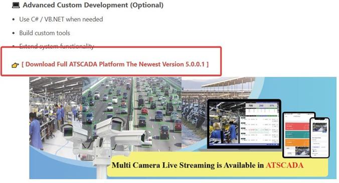
For the latest version of the ATSCADA installation guide, download the official ATSCADA .NET Solution Web Enabled package from the official source.
Download Source:
Visit the official link:
https://atscada.com/atscada-visual-studio-net-scada-solutions/
This ensures you receive the most up-to-date release with full integration of .NET libraries and the latest ATSCADA development tools.
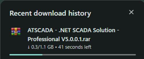
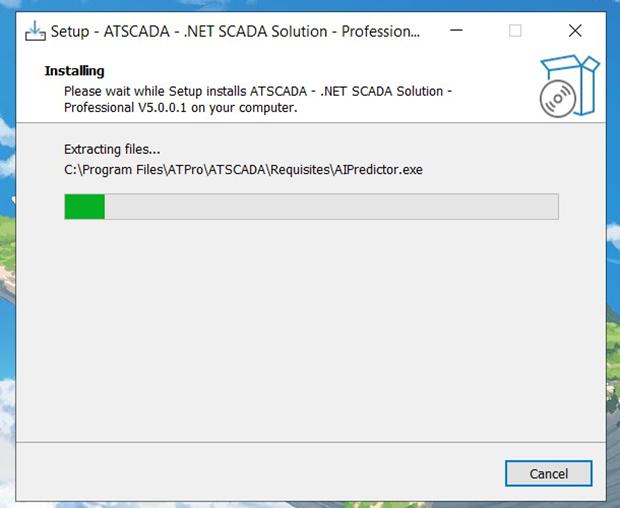
During the ATSCADA installation guide process, the browser download section will display the file currently being downloaded.
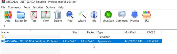
After the download is completed from the website, open the RAR file and run ATSCADA – .NET SCADA Solution – Professional V5.0.0.1.exe to continue the ATSCADA installation guide process.
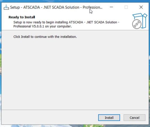
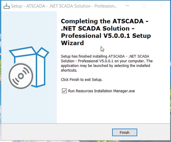
After the installation is completed successfully, the ATSCADA installation guide setup process is ready for the next configuration steps.
In the ATSCADA Installation Guide – Install IIS Web Server to Support ASP.NET and Host Web-Based Applications
This setup is mandatory in the ATSCADA installation guide so that Web Tools can interact with Web Services on the server, allowing the system to run on mobile devices such as iOS and Android.
Step 1: Enable IIS Features on Windows
Go to:
Control Panel > Programs and Features > Turn Windows features on or off
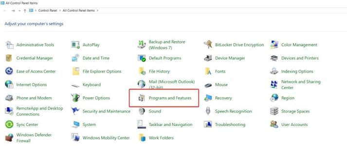
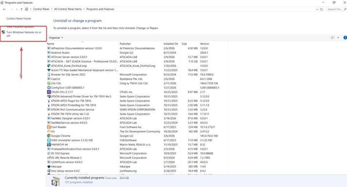
Locate Internet Information Services (IIS) and check the box to enable it during the ATSCADA installation guide setup process.
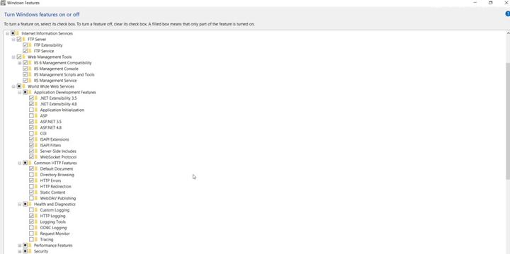
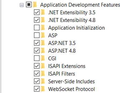
Important Note: To support ATSCADA running on the .NET Framework 4.5 platform, expand World Wide Web Services > Application Development Features and enable the following options during the ATSCADA installation guide process:
- .NET Extensibility (corresponding versions)
- ASP.NET (version 4.5 or later)
- ISAPI Extensions
- ISAPI Filters
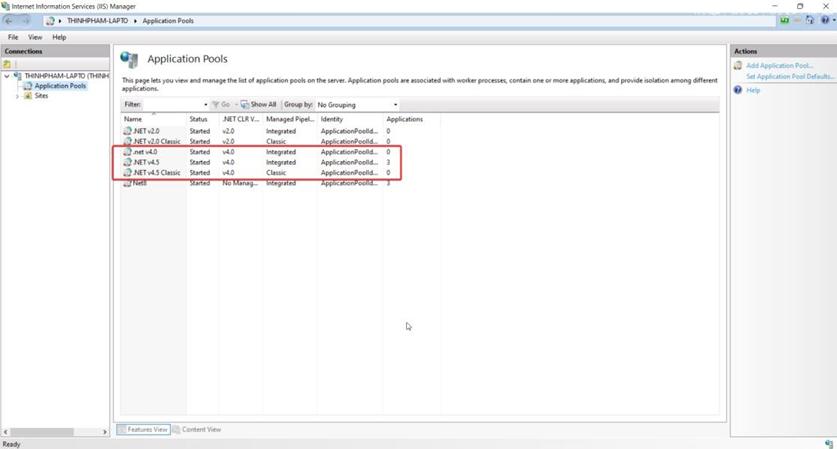
Step 2: Configure IIS to Support ASP.NET
After installation, open Internet Information Services (IIS) Manager to continue the ATSCADA installation guide setup.
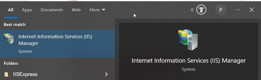
In Application Pools, verify that there is an application pool running the correct .NET Framework version required by ATSCADA (typically .NET 4.5) as part of the ATSCADA installation guide.
In the ATSCADA Installation Guide – Install the Database
This installation is mandatory in the ATSCADA installation guide to use data storage tools for querying, logging, and interacting with system data.
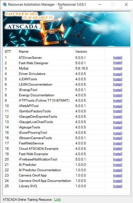
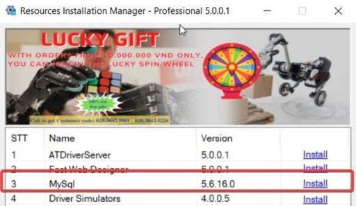
Quick MySQL Installation from the Resources Package
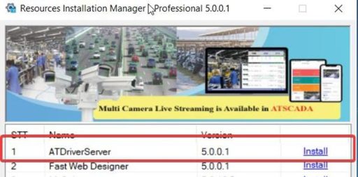
- Open Resources Installation Manager.
- Find MySQL (Version 5.6.16.0).
- Click Install.
- When the setup window appears, click Install and then Finish to complete the installation.
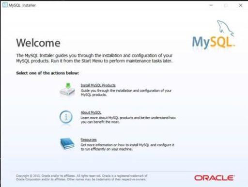
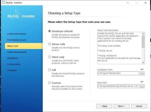
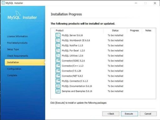
Select Install MySQL Products to continue the database setup in the ATSCADA installation guide process.
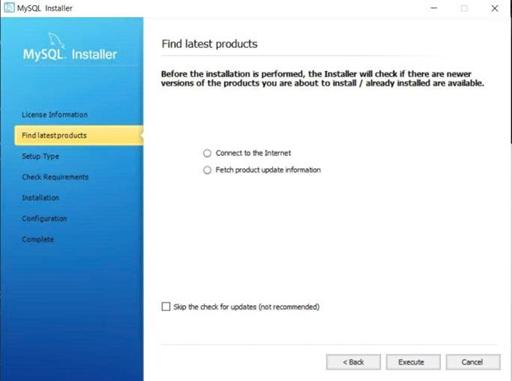
Next, select Execute to proceed to the next step in the ATSCADA installation guide process.
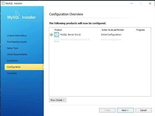
Select Next to proceed to the next step.
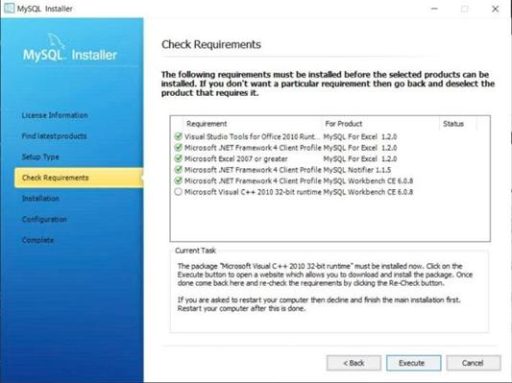
Select Execute to continue to the next step in the ATSCADA installation guide process.
Important Note: At this stage, the computer may require Microsoft Visual C++ 2010 32-bit Runtime (check the bottom option). Some systems will download it automatically. If your computer does not download it automatically, please visit the official Microsoft download link:
https://www.microsoft.com/en-us/download/details.aspx?id=26999
This is the official download source from Microsoft.
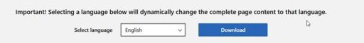
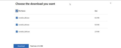
Check File Name, select all files, and click Download to continue the ATSCADA installation guide process.
After the download is completed successfully, return to the previous step and you will see the check mark turn green (similar to the others), then click Execute to continue the ATSCADA installation guide process.
Continue by selecting Execute.
Select Next to continue.
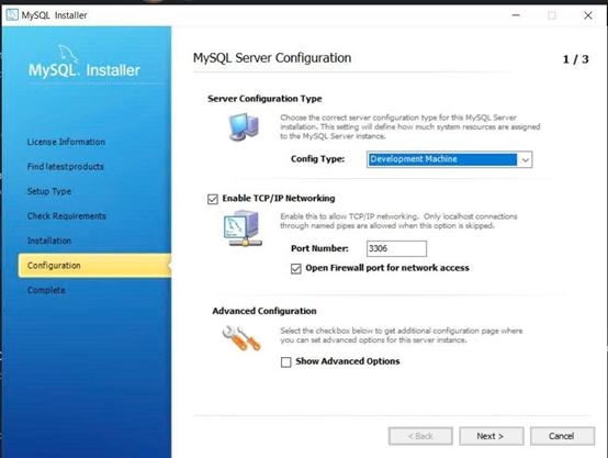
Select Next to continue.
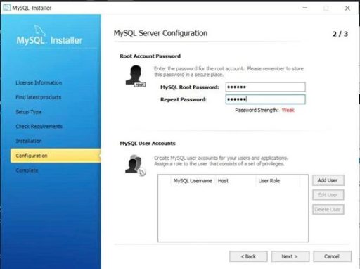
Important at This Step:
- MySQL Root Password is the password used to log in to the database. It is also the password that will be used to configure ATSCADA data storage tools connected to the database in the ATSCADA installation guide.
- MySQL User Accounts will remain root by default if left blank.
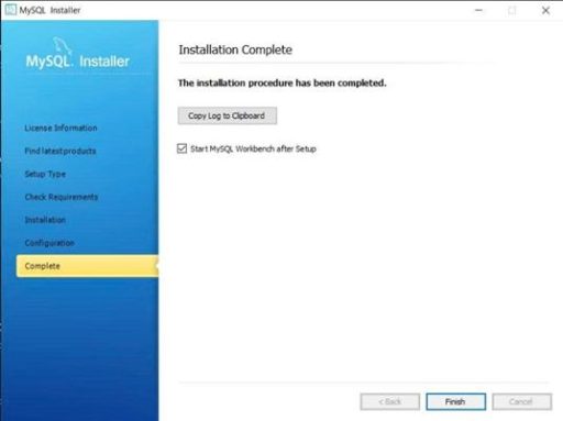
Finally, click Finish to complete the MySQL installation in the ATSCADA installation guide process.
After all installation steps are completed successfully, search for MySQL Workbench in the Windows search bar and open it.
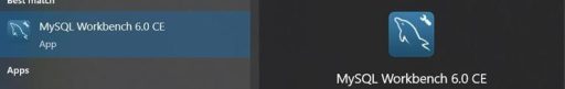
This is a GUI that helps users work with the database more visually and efficiently instead of using only query commands in the ATSCADA installation guide process.
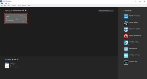
MySQL Workbench Overview
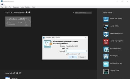
When opening MySQL Workbench for the first time, select the first available connection to continue the ATSCADA installation guide process.
Here, enter the password that was created in the previous step. If successful, you will gain access to the MySQL Workbench GUI as part of the ATSCADA installation guide process.
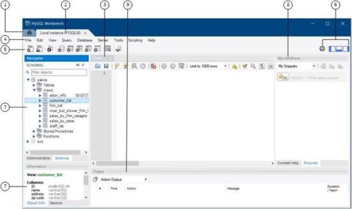
- Main Menu Bar (File, Edit, Database, Tools, Scripting, Help).
- Toolbar / Quick Actions Area (icon buttons for frequently used functions).
- SQL Editor: the area where you type and run SQL commands.
- Left Panel Header Section: the top area of the database structure browser.
- Schemas Tree (Left Navigator): displays database objects such as Schemas, Tables, Views, and more.
- Connection / Execution Controls (Top Right Corner): used for connection settings and running queries.
- Bottom Panel (Results / Object Details): shows query results or detailed information about the selected object.
- Right Panel (SQL Additions / My Snippets): stores and displays reusable SQL snippets for quick insertion in the ATSCADA installation guide
In the ATSCADA Installation Guide – Driver and Tag Management
-
ATDriver Server
ATDriver Server acts as the data acquisition server, serving as the communication bridge between field devices and monitoring software in the ATSCADA installation guide.
- Multi-Protocol Support: It can connect to various devices through common protocols such as Modbus RTU, Modbus TCP/IP, and dedicated drivers for Mitsubishi PLC, Omron PLC, and Siemens S7 Ethernet.
- Distributed and Cloud Capability: Communication between iDriver and ATDriver Servers is based on a service model, making distance transparent. This allows flexible operation on localhost, LAN networks, or through the Internet, providing strong support for cloud ATSCADA security systems and distributed SCADA applications.
- Scalability: Users can develop custom Native Drivers and integrate them into ATDriver Server to communicate with specialized devices.
- Read Functions in ATDriver Server: Supports reading real-time values from connected devices for monitoring and control purposes.
-
iTagBuilder
iTagBuilder is a dedicated tool used to define and manage tags within the ATSCADA system.
- Main Function: This tool performs the Serialize process for tag configurations to generate Tag Files, which are used by the system for data mapping and real-time communication in the ATSCADA installation guide.
- Workflow: These Tag Files are later processed by the iDriver component in the ATSCADA application through the Deserialize process, allowing the system to recognize and load data points in the ATSCADA installation guide.
- Role: It helps system designers organize, classify, and manage a large number of data variables from different devices in a structured and efficient way before integrating them into the programming and interface design environment.
To use ATDriver Server and iTagBuilder, users need to install them from the Resources Installation Manager package in the ATSCADA installation guide.
After successful installation:
Create your first demo project to become familiar with ATDriver Server and iTagBuilder for tag management in the ATSCADA installation guide.
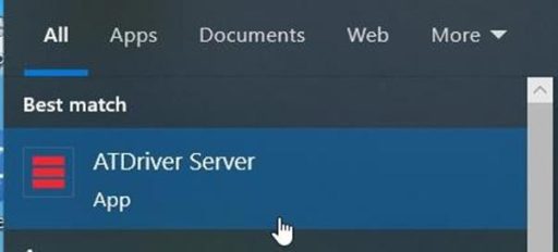
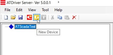
Step 1: Open ATDriverServer
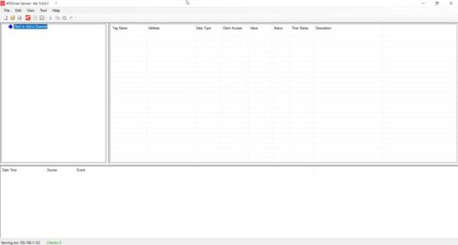
Step 2: Create a New ChannelCreate a new channel to manage drivers connected to peripheral devices in the ATSCADA installation guide.
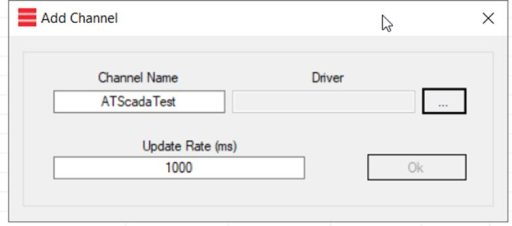
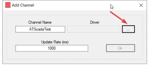
Select the Driver section to choose the appropriate driver in the ATSCADA installation guide.
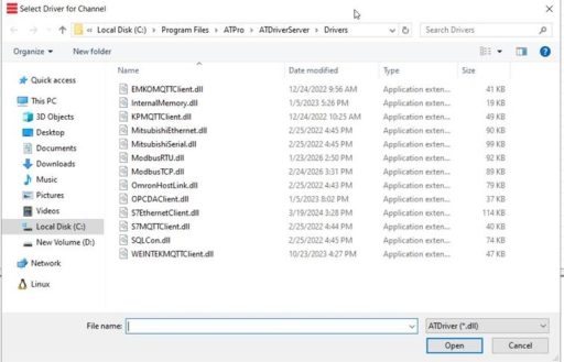
In this demo, select InternalMemory.dll as the driver to store tags at the hardware memory level of the computer running the server in the ATSCADA installation guide.
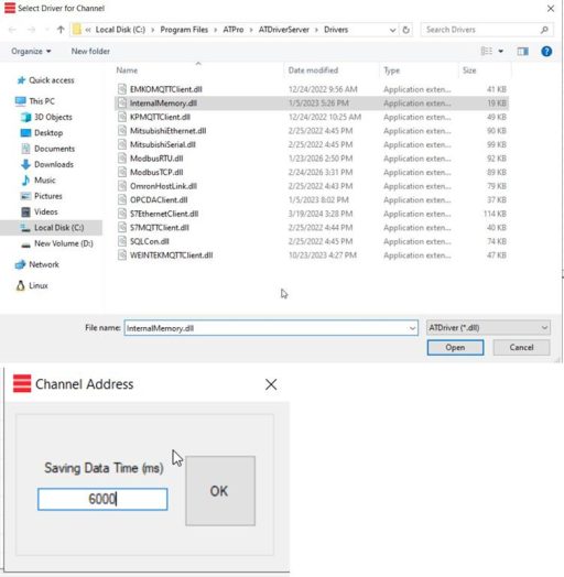
Saving Data Time (ms): Configure file saving time.
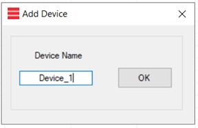
Step 3: Create a Device Under Channel Management
Click on New Device
Enter the device name:
Step 4: Create Tags Under the Device
Click on New Tag
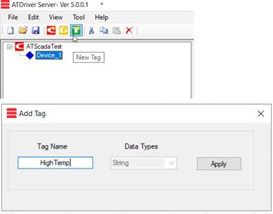
Data Types include options such as: Bool, Word, Short, DWord, Long, Float, DLong, Double, and more.
However, in this demo using InternalMemory, the default type is always String.
Click Apply, and the new tag will be created successfully in the ATSCADA installation guide.
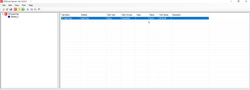
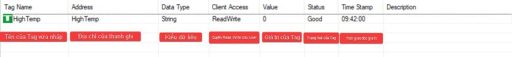
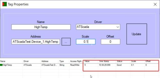
Annotations for each section in the Tag Details tab of the ATSCADA installation guide:
To write a Value to the tag, click Write Tag Value… in the ATSCADA installation guide
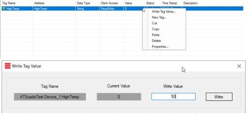 .
.
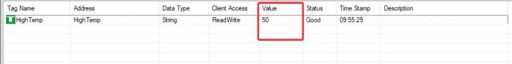
Enter the new value in the Write Value field and click Write to save it.
After a successful write, the Tag Value will be updated with the newly entered value in the ATSCADA installation guide.
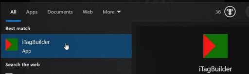
Step 5: Connect to iTagBuilder
Open iTagBuilder by searching for it in the Windows search bar as part of the ATSCADA installation guide.
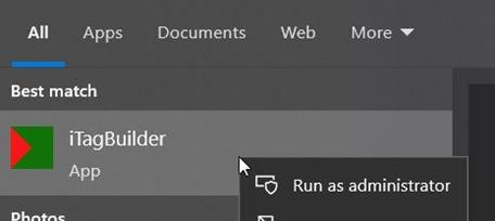
Run with administrator privileges.
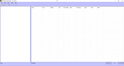
Click New Project:
![]()
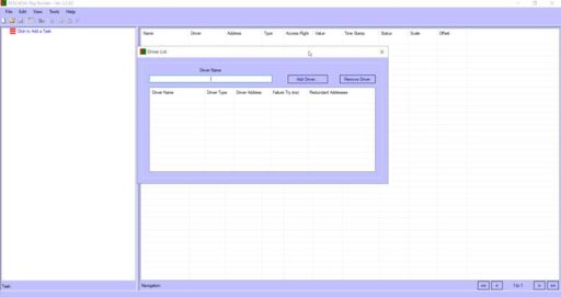
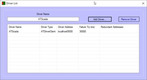
Enter DriverName, which is the name of the driver used for management in the ATSCADA installation guide.
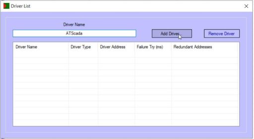
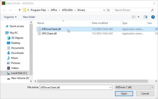
Click Add Driver… to select the driver that will manage iTagBuilder in the ATSCADA installation guide.
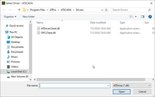
Here we will have 2 main drivers:
a) Function of ATDriverClient.dll
This file is a dedicated client-side component designed to work with the ATSCADA driver ecosystem.
- I/O Server Connection: It connects directly to ATDriver Servers (I/O Driver Servers).
- Multi-Protocol Support: Through this server, the application can collect data from devices using Modbus RTU, Modbus TCP/IP, and PLC brands such as Mitsubishi and Omron.
- Distance Transparency: Supports connections through Local, LAN, and Internet networks, allowing data from distributed ATDriver Servers to be transferred seamlessly to the application in the ATSCADA installation guide.
b) Function of OPCClient.dll
This file allows the ATSCADA system to expand communication with common industrial standards.
- OPC Server Connection: Acts as a standard OPC Client, enabling the ATSCADA application to connect and retrieve data from third-party OPC Servers such as Kepware.
- Compatibility: Helps integrate ATSCADA into existing OPC infrastructures without changing hardware or network architecture.
In this demo, we will select ATDriverClient.dll to work with the ATSCADA ecosystem in the ATSCADA installation guide.
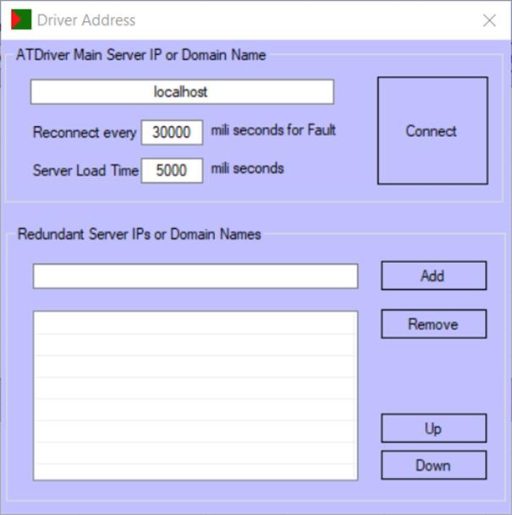
In the ATDriver Main Server IP or Domain Name field, you can enter localhost (the IPv4 address of the computer running the server) or the IP address of another machine acting as the server in the ATSCADA installation guide.
After successfully adding the driver, click on the Tools tab and select Import All :
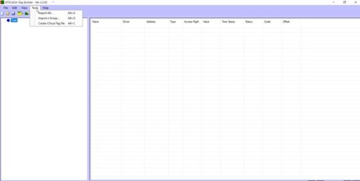
This is the Fast Import function of iTagBuilder, intended to quickly add tags that have already been added to the ATDriverServer.
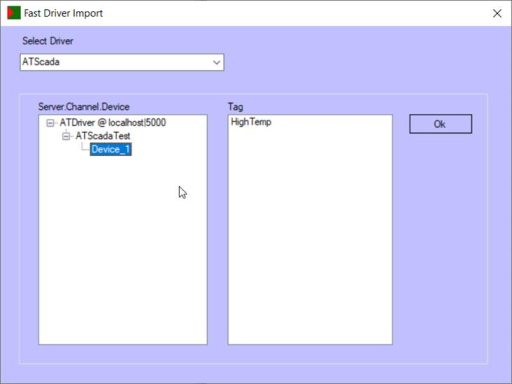
On this interface, we see the Channel – Device – Tag information that was added in the previous step.
Click OK to proceed with the import:
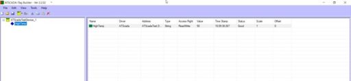
Here, there will be two different values compared to ATDriverServer: Scale and Offset.
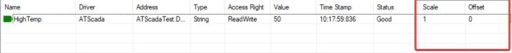
Scale and Offset are used to convert raw values from measuring devices such as sensors, PLCs, or analog modules into meaningful engineering values in the ATSCADA installation guide.
Formula:
New Value = Value × Scale + Offset
Example:
If the temperature sensor returns a raw value of 50, but the required display value must represent the real engineering unit, set Scale = 0.1.
The result will be:
New Value = 50 × 0.1 = 5
This is the actual engineering value with practical meaning.
After successfully setting up the display values, we proceed to save the file and register this TagFile.
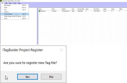
At this point, you can easily manage drivers and tags using the two applications ATDriver Server and iTagBuilder in the ATSCADA installation guide.
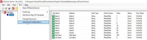
6. Advanced Functions of ATDriver Server
To open the configuration section, go to:
Tools > Advanced Configuration in the ATSCADA installation guide.
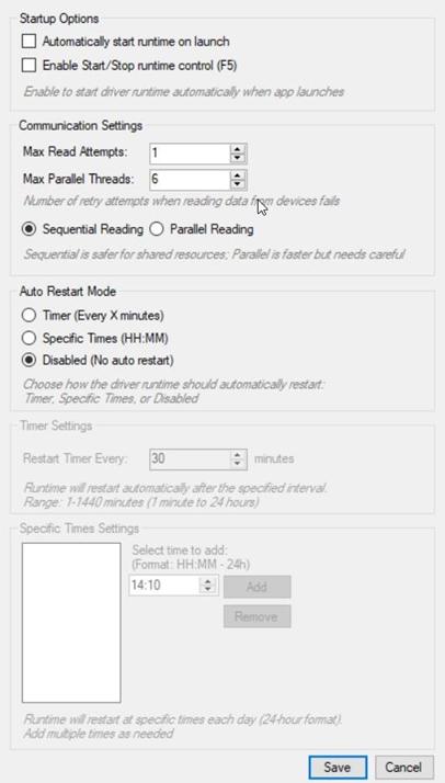
i) Startup Options Tab
- Automatically start runtime on launch: When Enable Start/Stop runtime control is enabled, ATDriver Server normally starts in Stop mode. If this option is checked, ATDriver Server will automatically start in Start mode when launched in the ATSCADA installation guide.
- Enable Start/Stop runtime control: Allows users to control whether ATDriver Server reads values or stops reading values on the server.
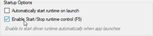
When this function is enabled, ATDriver Server will display an additional Start/Stop button on the main screen, allowing users to control whether value reading is active or paused in the ATSCADA installation guide.
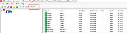
As shown above, all tags configured in ATDriver Server currently have Value = null and Status = BAD because the server reading state is set to Stop.
Proceed to enable ATDriver Server to read values again in the ATSCADA installation guide
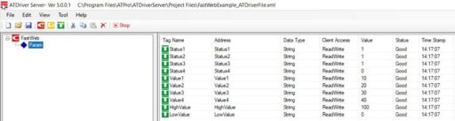
When the status changes from Stop to Start, the tag values are read and updated in ATDriver Server.
ii) Communication Settings Tab:
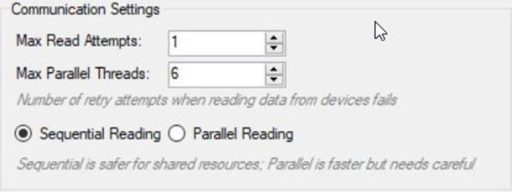
1 .Max Read Attempts: 1 (Number of Read Attempts)
- Meaning: The number of times the system retries sending a data read request to the device if the previous read fails due to network noise, device busy status, timeout, or other communication issues.
- This setting defines the retry attempts when reading data from devices fails in the ATSCADA installation guide
- Analysis: With the value set to 1, the system uses a fail-fast approach. If a read command receives no response, the system records the error immediately and skips the request without retry delays.
- Practical Use: This setting is suitable for highly stable local networks or systems with a very fast polling cycle, where the next scan occurs within milliseconds. However, for noisy environments such as RS-485 or wireless networks, the value is commonly increased to 3 to prevent temporary connection drops from interrupting data collection in the ATSCADA installation guide.
2. Reading Method: Sequential Reading Selected
- Sequential Reading: The system sends request #1, waits for the device response, then sends request #2.
- Application: This is the safest and most required option for shared physical communication lines such as Serial RS-485 (for example, Modbus RTU). Sending multiple requests simultaneously on this line may cause signal collisions and corrupt the data packets. This mode also protects older field devices from being overloaded with requests.
- Parallel Reading (Not Selected): Sends multiple read requests at the same time. This is ideal for Ethernet-based communication such as Modbus TCP or OPC UA, significantly increasing data acquisition speed, but it requires the target device to support multi-threaded processing in the ATSCADA installation guide.
iii) Tab Auto Restart Mode:
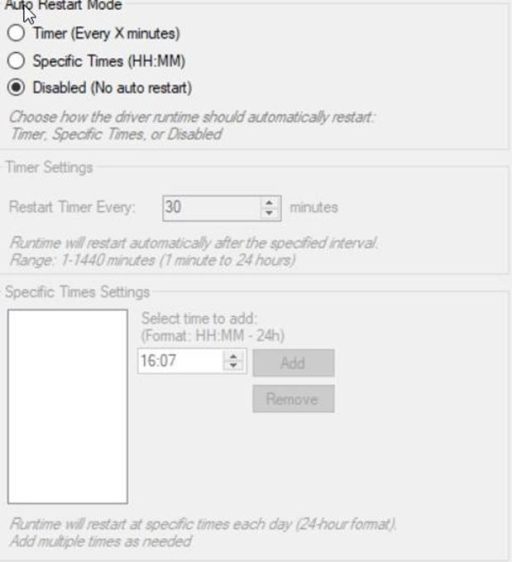
1. Auto Restart Mode Classification
The system provides three main Auto Restart Mode options in the ATSCADA installation guide:
- Timer (Every X Minutes):
Restart based on a scheduled time interval. - Specific Times (HH:MM):
Restart at specific times configured during the day. - Disabled (No Auto Restart):
No automatic restart enabled (default mode).

2. Detailed Configuration and Technical Parameters
2.1 Timer Settings
- Restart Timer Every: 30 (default)
- Range: 1 – 1440 minutes (maximum 24 hours)
Description: Defines the number of minutes between each automatic system restart.
Practical Applications:
- Used when the driver shows signs of memory leaks over time.
- Suitable for systems that run continuously without a fixed downtime schedule.
2.2 Specific Times Settings
- Format: HH:MM (24-hour format)
Description: Allows you to configure a list of fixed times for automatic restart in the ATSCADA installation guide.
Example:
- 03:00 (restart at 3:00 AM every day)
Practical Applications:
- Suitable for system maintenance during off-peak hours.
- Helps avoid affecting production operations.
2.3 Add / Remove
- Functions:
- Add new restart times
- Remove configured restart times
Description: Provides flexible management of scheduled restart times.
3. Operational Logic Analysis (For Engineers)
Important Note:
When the Driver Runtime performs an automatic restart, it may temporarily interrupt the following processes for approximately 2–5 seconds, depending on the hardware configuration:
- Data Acquisition
- Data Transmission to ATDriver Server
A. When to Use Timer Mode?
This mode is preventive maintenance oriented. Recommended when:
- RAM usage gradually increases and is not released properly.
Example Configuration:
- 720 minutes (12 hours) → helps clear memory periodically.
B. When to Use Specific Times?
This is the most professional and optimized method for industrial environments.
Advantages:
- Synchronizes system maintenance schedules.
- Prevents restart during critical operating periods such as:
- Logging electrical values during peak hours in the ATSCADA installation guide.
C. Recommended configuration
- Testing Systems:
→ Keep Disabled mode enabled. - Production Systems:
→ Use Specific Times mode.
Recommended Restart Times:
- 00:00 (start of the day)
- 03:00 (off-peak hours)
Objectives:
- Ensure the driver remains stable at all times.
- Optimize performance for the new working day in the ATSCADA installation guide.
👉 Learn More about ATSCADA Software

ATSCADA - Smart SCADA Software with AI Predictor & Blockchain. ATSCADA is an advanced SCADA software platform for real-time monitoring, intelligent control, and efficient data acquisition. It is ideal for Industrial IoT (IIoT), smart cities, integrated automation systems, and Agriculture 4.0. With a built-in AI Predictor, ATSCADA enables predictive analytics to detect issues early, optimize performance, and reduce downtime. The integration of Blockchain technology ensures secure, transparent, and tamper-proof data management. Highly scalable and easy to integrate, ATSCADA is trusted by businesses to enhance productivity, strengthen cybersecurity, and accelerate digital transformation.
Related articles
ATSCADA iStreamCameraTools – Industrial IP Camera Integration and Real-Time Video Monitoring
The iStreamCameraTools toolkit enables the connection of ONVIF-compatible cameras to receive camera streams and display [...]
Jun
OPC Server Connection Guide
Overview The ATSCADA ecosystem provides exceptional flexibility for integrating data from third-party OPC Servers (such [...]
Jun
Common ATSCADA Errors and How to Fix Them – FAQ for ATSCADA Tools and Systems
Issues Related to ATDriverServer & iTagBuilder Software Why Does ATDriverServer Not Open? There are two [...]
May
ATSCADA Hospital Temperature and Humidity Monitoring Alarm System Project
Requirements: The system includes three monitoring areas: the pharmacy, inpatient warehouse, and cold storage, following [...]
May
ATSCADA CookBook: Complete Guide to System Architecture, Tools, Installation & Troubleshooting
The ATSCADA Training book is an essential navigation structure that helps users access all major [...]
Apr
ATSCADA Power Management System
Requirements: There are 3 areas that require power management, including a factory, a residential zone, [...]
Apr